DoF - a Robotiq Community
Warning sign
The Dof Community was shut down in June 2023. This is a read-only archive.
If you have questions about Robotiq products please reach our support team.
Annick_Mottard

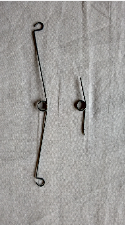
@Tyler_Berryman this part is indeed very narrow for the Vision system. 

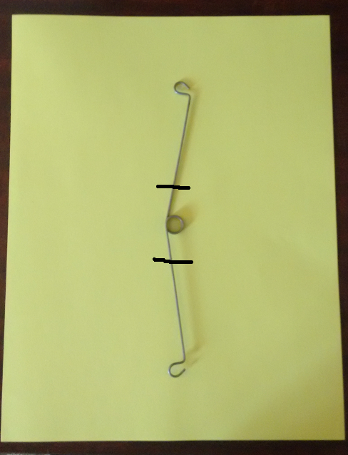
Here is one thing you could try: cut the spring so that you only keep the center part - where the loop is. When defining the Snapshot position, you should try to be as close as the application allows (the closer you can go with the Wrist Camera is 70 mm from the workplane).
zoom

Therefore, you would teach the center part of the object. When doing the part detection, the Vision system will look for that center part of the object. 

Tyler_Berryman

@Annick_Mottard

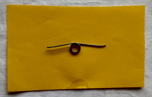
Thanks for the information! As you suggested, I cut the part to create a smaller part. Here is a picture of the modified spring. 
zoom
The next step to teach this part to the vision system was setting up a new snapshot position. I positioned the camera at a height of about 130mm over the part and saved the position during the "Define Snapshot Position" step. From this position, the calibration grid does not fit in the camera's field of view, so I moved the camera up in order to see the entire calibration board in the camera's field of view, then I pressed the "Calibrate" button. This allows you to set a snapshot position that is close to the part and still get a good calibration. This also means that your snapshot position and the calibration position do not need to be the same position. 

The next step consisted of teaching the part to the vision system. To do this, I used a smaller piece of yellow paper to provide the background needed to teach the part. I tried using a letter size piece of paper, but I was getting an error saying that the object was not present on the background. This problem was occurring because the background was much too large for the size of the part, so the vision system was having a hard time identifying the pixels corresponding to the part. To workaround this problem I cut the piece of paper to create a better ratio between the background and the part.

zoom

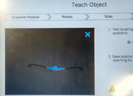
From here I taught this part to the vision system using the standard process. The vision system was able to create an image template of the part and was able to identify this section of the part in the original spring. 

zoom

As you can see, the image template is being matched to the original part! This means that if parts are too large for the vision system, you can teach a specific feature to the vision system. Then when you put the entire part in the camera's field of view, the vision system will be able to recognize the feature that you taught.