
 matthewd92
@ArigatoMrCoboto we generally deploy our robots on a pedastal stand. It’s a 6” column of 8020 material that is secured to the floor. This allows us to have maximum joint mobility, we have robots that work high and low using these stands. We have also mounted a couple of robots directly to the table where the work is being done. This works well when the joint positions can accommodate being on a table top as you don’t worry about any misplacemrnt or movement between the robot stand and the workpiece. I’d say though that 85% of all our robots in the field are on stands that sit in front of the equipment roughly where the operator used to stand.
 ArigatoMrCoboto
Matthew,
Thank you very much indeed for the response.
Patrick
 mhowe
mhowe

 maxlavigueur
At Vention we have over 40+ public Robot Stand assemblies and have mounting plates for UR3, UR5 and UR10.
Check them out for inspiration; you can always customize the design to your liking, or create your own!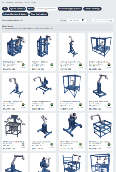
Max
PS: if you think a part is missing from our Parts Library and would be beneficial to others, we would be happy to publish it.
 vhosouza

Hi all,
I'm currently working on implementing cobots in our factory. What are some the best ways to mount a robot? The cobot is going to be used for a pick and place application. We've tried mounting the robot to a beam above the work space, also placed the cobot on the wall. Both ceiling and wall have limited the robots joint mobility. We may try placing the robot in front of the table (like the operator). What methods has the community adopted for mounting a cobot? What type of mounting does the Path feature work best for? Thank you for your time.
Patrick