
 louis_bergeron
@Puolikas
I think you can't use MoveJ in this case. MoveJ is a motion in Joint space, not in Cartesian space. It means, there is no x,y,z coordinate. The coordinates are in degrees for each joint for a MoveJ. You will also see that acceleration and speed are represented in degrees/second and degrees/sec2. It means MoveJ is neither in the Base coordinate. Asking the robot to put joint number 2 at 35 degrees, for example, it means it's always at the same place in space. That's why it look like in base coordinate because it's a fixed position in space. It's a fixed angle for each joint. The base is also in Cartesian space with X,Y and Z. To use Cartesian coordinates like X,Y,Z, I think you must use MoveL or MoveP.
 matthewd92


 K_Bing
 Tesfit
Any update about reteaching the plane easily? I am working on a mobile station where a positional error can happen due to then nature of the design and I am using a feature plane to program the waypoints. The problem I am having is when I reteach the plane it is difficult to get an accurate position of the plane.matthewd92 said:Fortunately I have to do this for a customer so will be working on it over the next week or so as we are deploying the robot. I am not sure yet how I would go about reteaching the plane feature easily, have some ideas but have not completely baked them all the way through and am just pulling a robot out of the box this week for the test. Hard to do what I am planning to do on the simulator. I'll keep you posted though.
 cobottiukko
@Tesfit Our customers are using Robotiq's Contact offset feature a lot. When using it, no need to program any changes even the mobile station is not exactly at the same position as it used to be when implemented. All the waypoints are programmed in Feature Point and Robotiq's Contact offset will adjust the Feature point so all the waypoints will be moved relatively same amount.Tesfit said:Any update about reteaching the plane easily? I am working on a mobile station where a positional error can happen due to then nature of the design and I am using a feature plane to program the waypoints. The problem I am having is when I reteach the plane it is difficult to get an accurate position of the plane.matthewd92 said:Fortunately I have to do this for a customer so will be working on it over the next week or so as we are deploying the robot. I am not sure yet how I would go about reteaching the plane feature easily, have some ideas but have not completely baked them all the way through and am just pulling a robot out of the box this week for the test. Hard to do what I am planning to do on the simulator. I'll keep you posted though.
Here you can see the idea: https://www.youtube.com/watch?v=Bs_MQslF_v8&t=14s All credits to Ralph W. Earl Company for this awesome video! ( @bcastets It would be nice if you could have same kind of video in youtube as a public video)
Below is also a good application video from our customer where robot is on mobile platform (EasyRobotics Flex) and the robot is moved in daily basis. "Reprogramming" is done by the Robotiq Copilot. Human just places the robot somewhere near the machine and rest is done automatically.
Application video: https://www.linkedin.com/posts/mrliljamo_robotti-astui-t%C3%B6ihin-purkamaan-tuotannon-activity-6780388942060539904-zqh7
Robotiq has a great learning platform where Contact offset function is explained in depht. https://elearning.robotiq.com/
 bcastets
@cobottiukko
Thank you for your suggestion. I will try to work a video to show a use case of Contact Offset function.
At the moment the best reference we have is probably our elearning video:
https://elearning.robotiq.com/course/view.php?id=7§ion=14
cobottiukko
Thank you! That's true but the problem is that those eLearning videos cannot be shared or embedded since it requires to be signed at eLearning.bcastets said:@cobottiukko
Thank you for your suggestion. I will try to work a video to show a use case of Contact Offset function.
At the moment the best reference we have is probably our elearning video:
https://elearning.robotiq.com/course/view.php?id=7§ion=14
 colbyj
I've been trying to do this for a similar application recently. I see how to change the base feature to variable in polyscope- but then how do you use it?matthewd92 said:@Puolikas have you ever tried making the Base feature a variable? You could then change the base feature frame of reference, this might be what you are looking for. Basically in your before start you could ask for some offsets in the X, Y ad Z direction and then use those offsets to offset the base coordinate system.
Is this more along the line of what you are looking for?
We're attempting to shift our x-y orientation, so that we can program one set of movements as relative moves and adjust the orientation as need be. I wrote a script that takes the difference in angles between two waypoints (one defined as the "start" orientation, and one as the "new") and adds them to the initial TCP- defined in the Installation (and manually created into a variable in BeforeStart).
The issue is, however, that these translations aren't correct, since get_target_tcp_pose (and the other ways of pulling the pose value, from what I can tell...) is WRT the base frame, not the flange frame (which the TCP rotation's are WRT).
So I'm wondering, could we make the base feature a variable, and add our angle shifts to it to achieve the intended rotation? And if so, how would we access the base feature in URScript?
Thank you in advance!
colbyj
colbyj said:I've been trying to do this for a similar application recently. I see how to change the base feature to variable in polyscope- but then how do you use it?matthewd92 said:@Puolikas have you ever tried making the Base feature a variable? You could then change the base feature frame of reference, this might be what you are looking for. Basically in your before start you could ask for some offsets in the X, Y ad Z direction and then use those offsets to offset the base coordinate system.
Is this more along the line of what you are looking for?
We're attempting to shift our x-y orientation, so that we can program one set of movements as relative moves and adjust the orientation as need be. I wrote a script that takes the difference in angles between two waypoints (one defined as the "start" orientation, and one as the "new") and adds them to the initial TCP- defined in the Installation (and manually created into a variable in BeforeStart).
The issue is, however, that these translations aren't correct, since get_target_tcp_pose (and the other ways of pulling the pose value, from what I can tell...) is WRT the base frame, not the flange frame (which the TCP rotation's are WRT).
So I'm wondering, could we make the base feature a variable, and add our angle shifts to it to achieve the intended rotation? And if so, how would we access the base feature in URScript?
Thank you in advance!
Turns out I was looking for the Base variable in the installation variables, and didn't see it in the program variables tab at first (I have many variables being defined/stored).
This approach however would shift the location of the starting position the intended amount, but not the actual direction of the motions. Effectively, the robot would just rotate 90 deg. about its base and continue the same pattern in the original direction. I likely messed something up, but we're trying this method instead:
The new approach we're trying is a variable Point Feature as the reference, so that we can orient all of our programs based on some initial point of that section (program is relative movements for a "section", based on some initial position anyways- so this would be much easier to figure out than a plane).
An example would be:
Loop_1 = 0 #Set Loop Counter at 0global p_ileft = Point_1 #def initial pose, Point_1 is a Point Feature initialized to = the initial tool positionglobal p_iCenter = pose_trans(p_ileft, p_via) #def center poseglobal p_iright = pose_trans(p_ileft, p_to) #def end posesleep(0.01)while (Loop_1 < btm_passes): movec(p_iCenter, p_iright) stopl(a) sleep(0.01) if Loop_1 < (temp_btm_passes): movec(p_iCenter, p_ileft) #Return on non-last loops stopl(a) sleep(0.01) else: break #Stay on Right Side for Last Loop end Loop_1 = Loop_1 + 1endWe call our script files (within 'script code' nodes in polyscope) within a MoveL, with the feature set to Point_1_var. It works as intended when we manually set the Point_1 Feature to = the tool, and using the pose_trans function (I've been going back and forth between when to use trans or add...). However, if I try to change the initial waypoint and run global Point_1_var = get_target_tcp_pose(), the feature won't re-initialize to the new initial TCP position. Are these changes happening internally and not being stored? Or are the changes not being made?
Also, can we redefine these Positions using script? Such as, instead of teaching Point Features for each initial point of the section (we're going to have many sections) and modifying the script files to refer to each different Point Feature, could we teach each as a waypoint, move to that waypoint, and execute Point_1_var = get_target_tcp_pose()?
I'm thinking that the waypoints in this case would have to be in a separate Move command, relative to the base instead of the Point Feature (as the feature would be changing)...

Hi.
What is the best way to use the feature plane?
My rig is Universal Robots UR10, Robotiq wrist camera and Robotiq 2F140 Gripper.
I have a portable assembly station and I want to move it around, take it to storage and put it back in a different place etc.
Now what I have done is to make a plane feature, points representing the corners of the station. Then in program I choose the feature plane under the MoveL command. Everything going great when the program is very simple.
I get the problems when the program is complicated. I cannot use MoveJ command (cannot choose the plane feature). Then in palletizing when I make rectraction after I have gripped the part the added Waypoints make weird moves. Like they are calculated from the Base feature.
Everything is resolved when I know how to move the base feature origin to the work origin before programming.
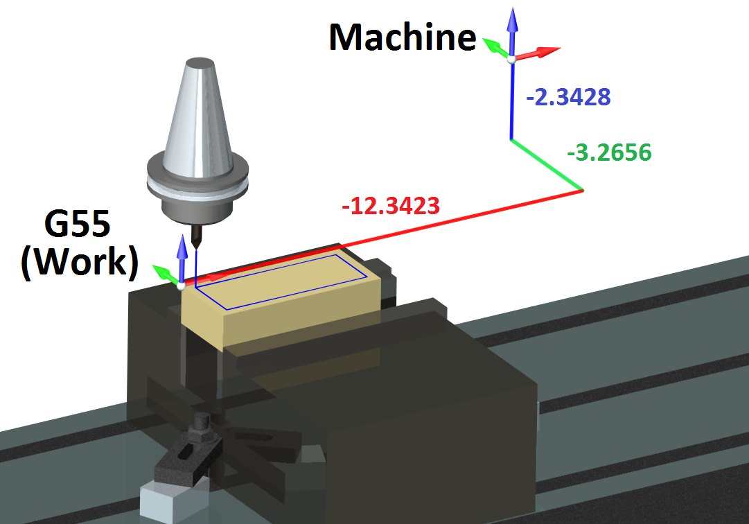
This method is widely used in CNC-machining:
So we have the Machine origin and then we tell the Machine where the origin of the part is. Then if we tell the Machine to move to X0,Y0,Z0 it will go to the origin of the part, not the Machine origin. This is like using feature plane, but every move is automatically related to part origin. So if you just make a MoveL command X0,Y0,Z0 without choosing the feature plane, it should go to part origin, not to the base feature origin.
If you can help me with this I would be very thankful! At our company (Oulu University of Applied Sciences) we have 30 students, 10 groups, sharing 4 UR-robots. That means robot cells moves all the time and without easy way to move the origin of the program, students have to always show the moved waypoints all over again. That can be frustrating..
Please feel free to ask more specifics if you need. :smiley:
/ Lassi Kaivosoja - Project Engineer OUAS