Home Applications

Discussion

Left ArrowBack to discussions page
lakshmip001lakshmip001 Partner Posts: 41 Apprentice
edited December 2016 in Applications
Hi, I need to make either a spiral motion orelse create a small circle and increment it gradually using offsetting for the application. The tool is small like a pen end. 
Thanking you in advance.

Best Answer

Comments

  • Tim_SmithTim_Smith Posts: 38 Apprentice
    edited December 2016
    @lakshmip001
    If I understand correctly, you are looking to complete a motion that looks like the following image:

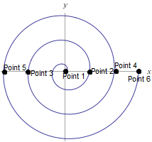
    In the past, I have programmed spiral moves using the CircleMove function. To complete the spiral move depicted by the image, I would use the following series of CircleMoves:
    • CircleMove from : Point 1 to Point 2
    • CircleMove from : Point 2 to Point 3
    • CircleMove from : Point 3 to Point 4
    • CircleMove from : Point 4 to Point 5
    • CircleMove from : Point 5 to Point 6
    I understand that this method is quite time-consuming and is not very flexible but it worked quite well. I think the same motion could be programmed using a pose for the center point and an offset that can be added to the pose. I'll try to write a program for this and post it within the next few days. I hope this helps!

  • matthewd92matthewd92 Founding Pro, Tactile Sensor Beta Testers Posts: 1,267 Handy
    We wrote a UrScript for doing just this. You give it the starting ID and the step André you want and the number of degrees of rotation. Let me see if I can find it and I'll copy it in here. 
  • matthewd92matthewd92 Founding Pro, Tactile Sensor Beta Testers Posts: 1,267 Handy
    @Tim_Smith sorry about this being so late, I forgot to upload it before.  Here is a URscript that we wrote to do an Euclidean Spiral on the robot


    def spiral(angleToStep, startRadius, stepSize=.001, maxAngle=100000, maxRadius=100000, v=0.25, a=1.2):
      global r = startRadius
      global x = 0
      global z= 0
      global y =0
      global pos = p[0,0,0,0,0,0]
      global startPos = get_actual_tcp_pose()
      if maxAngle == 100000 and maxRadius == 100000:
        popup("Must specify either a max radius or a max angle")
        halt
      end
      global phi = angleToStep
      while phi < maxAngle and r < maxRadius:
        phi=phi+angleToStep
        x=cos(d2r(phi))*r
        y=sin(d2r(phi))*r
        pos[0]=pos[0]+x
        pos[1]=pos[1]+y
        r=r+stepSize
        if phi>= maxAngle or r>=maxRadius:
          movep(pose_trans(startPos,pos), a=a, v=v, r=0.0 )
        else:
          movep(pose_trans(startPos,pos), a=a, v=v, r=.00001)
        end
        sync()
      end
      #popup("Spiral has finished")
    end
    
    
    To call this from the robot, you would simply add a script node to the program preceded by the starting waypoint in a move, this is where it will start the spiral from.  There are a number of optional parameters in the method call including maxRadius, maxAngle, stepSize, acceleration (a) and velocity (v).  To call any of those just follow the example below.  One of either the maxRadius or maxAngle must be called, if not a pop-up will come up telling you what to do

    I tried to load the file on there but it keeps saying the file type is not allowed....

    The script line in the robot is: spiral(45, .025, Base, stepSize=.005, maxRadius=.15)

    So calculate the spiral every 45 degrees with a starting radius of 25 mm, a step size of 5 mm at each of the step angles and a max radius of 150 mm.  Generally we are using this in a very fine way with step sizes in the 0.1 mm range and a starting radius of 0 or .1 mm.  It is just really hard to see that on the screen.  Useful inside of a force node to find a hole for instance for inserting a pin into a hole when the exact location may change slightly.  We have also written a similar one that calculates a z dimension so that it doesn't spiral in a plane, it spirals in cylindrical fashion, this was very useful for sliding a part over a pin.  In that one we rewrote it some so that the spiral didn't grow in the x,y plane but rather was a helix in the z axis.

    It also uses the TCP to calculate the plane that the spiral is in, so its in the x,y plane of the tool flange.  This allows the robot to change positions and still perform the spiral.

    Here is a short clip of the script running in the simulator.
    al is i

    Hope this was helpful
  • lakshmip001lakshmip001 Partner Posts: 41 Apprentice
    ok thanks alot .
  • matthewd92matthewd92 Founding Pro, Tactile Sensor Beta Testers Posts: 1,267 Handy
    You're welcome
  • lakshmip001lakshmip001 Partner Posts: 41 Apprentice
    matthewd92,

    I am new to testing a robotiq vision with a feeder.First I am gonna test without a feeder. Can I know what are things to be known for testing a feeder?

    Thanking you in advance.

    Warm Regards,
    Lakshmi Prasanna. 
  • matthewd92matthewd92 Founding Pro, Tactile Sensor Beta Testers Posts: 1,267 Handy
    @lakshmip001 what kind of feeder, the biggest challenge we saw was figuring out your control logic, what's going to tell the feeder when it needs to run or not. We use fix mount cameras with the feeders so that we can be monitoring the feeder the entire time and making decisions on what to do. We return from the camera the number of parts that we see on the table to make decisions as well as a couple of other factors. 

    I'm not sure with the robotiq camera if you can get a variable with the total number of parts that are seen. If you can, that's one good way to control as you can leave the table alone until you get down to just a couple of parts. In our case one or two short vibrations will usually bring parts into the field of view. Our typical table vibration is 150 milliseconds with a 1 second delay before taking an image to give the parts time to stop moving but that would also depend on the weight and size of the parts. 

    Did that answer your question?
  • lakshmip001lakshmip001 Partner Posts: 41 Apprentice
    matthewd92 I am suggested to use Asyril Feeder.
  • lakshmip001lakshmip001 Partner Posts: 41 Apprentice
    Thanks a lot.
  • salexsalex Posts: 1 Recruit
    @matthewd92 would you have to write the "stop" (whatever condition it may be) into the spiral script if it was searching for a bore to insert a pin? Or could you have it as an if then statement that checks continuously before executing the spiral script?
  • Tyler_BerrymanTyler_Berryman Posts: 122 Handy
    @salex You can download the Spiral Search skill, it is a URCap that you can install on the robot's controller. The skill will allow you to execute the Spiral Search and the stop conditions are built in. Here is a link to the download page : https://skills.robotiq.com/SPIRALSEARCH/1
    Tyler Berryman
    Robotiq Integration Coach
    [email protected]
    1-418-380-2788, option 3
  • matthewd92matthewd92 Founding Pro, Tactile Sensor Beta Testers Posts: 1,267 Handy
    @salex we use an if statement or a loop statement and have the box checked for check continuously. This basically turns them into while statement and then we use the condition as something like force greater than some value so that when your find the hole the force should drop dramatically and then you can issue a stopj() or stopl() command. Just remember to include a deceleration value in the command. 

    If youre using the robotiq product you can download the skill as Tyler mentioned above but the methods I’ve been describing here would work with any brand as well as the built in force feedback of the robot
Sign In or Register to comment.
Left ArrowBack to discussions page