Here is the program I used for the demonstration:
 Program
   BeforeStart
     parts≔0
   Robot Program
     MoveJ
       Waypoint_1
     Pallet
       Pattern: Line
         StartPos_1
         EndPos_1
       PalletSequence
         Approach_1
         Gripper Move 70%
         Waypoint_14
         Gripper Close
         Waypoint_15
     MoveJ
       Waypoint_1
     Camera Locate
       If parts≟0
         MoveL
           Waypoint_3
           Waypoint_2
           Gripper Open
           Waypoint_3
       If parts≟1
         MoveL
           Waypoint_5
           Waypoint_4
           Gripper Open
           Waypoint_5
       If parts≟2
         MoveL
           Waypoint_7
           Waypoint_6
           Gripper Open
           Waypoint_7
       If parts≟3
         MoveL
           Waypoint_9
           Waypoint_8
           Gripper Open
           Waypoint_9
           Halt
     Set parts=parts+1
 Catherine_Bernier
@lakshmip001 You can find all the details about the specifications of the camera like the smallest part that can be detected on our support website.
Here is the page concerning the size of parts: http://support.robotiq.com/display/RVS/6.3+Vision+System+Specifications
The minimum dimension detectable is 10% of the field of view, so 7.5 mm would be the smallest dimension the camera can detect.
This would work for the part dimension you have.
@Catherine_Bernier Yeah I saw the specifications of camera. So I tried experimenting with the camera at different heights and with black circle on paper with various daimeter varying from 3cm, 2cm and 1cm. But it was able to detect only 3cm diameter circle. From the application given above I understood that there should be object which covers 10% FOV and then only it is able to detect 6mm circle. Is my conclusion correct. If not please advise me.
Thanks
 Catherine_Bernier
@lakshmip001 In order to see the smallest dimension you'll need to use the lowest position of the camera relative to your work plane, so about 7 cm for the UR5.
 Tyler_Berryman
@lakshmip001 There is not enough contrast between a black object and a white background. Here is a post that explains why : http://dof.robotiq.com/discussion/comment/1224. Essentially, white and black are different intensities of the same color.
However, I did try teaching a black circle on a white piece of paper and it worked fine. Here is the setup that I used: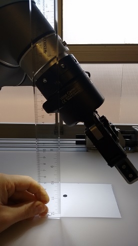
The camera is about 16cm above the object. Here is the detection score that I obtained with this snapshot position.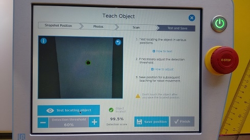
And here is the size of the black circle that I drew on the white piece of paper :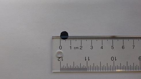
As you can see the black dot is about 7mm in diameter.
The position according to the base is:
X = 347.04mm
Y = -309.92mm
Z = -4.70mm
Rx = 0.0242
Ry = -5.3594mm
Rz = 0.0173
Try this and let me know if it works!
Thanks Tyler_Berryman for the help. It is really useful. But I was unable to teach object using white paper with black circle. But I taught the the circle of 7mm using yellow background with blue circle. I could use the same to detect the b
 David_Levasseur
@lakshmip001, you might need to set your detection threshold a tad higher to prevent false detection. At 40%, the system can detect your object even if it not there. Look at the score you get when a false detection occurs during object testing and set your threshold level higher than this score.
Hi David_Levasseur ,The object I need to detect is little reflective and thin sheet and I need to detect one object from four objects on the background. So for detection of one object from the four and then one from three, then one from two. It needs a threshold of 40%. And vague object detection is taking place at a detection threshold of 42%. I tried by increasing threshold. If I increase detection threshold, object is not detected when four are placed at a time.
Kindly please provide some suggestion.
Thanking you in advance.
Warm Regards,
Lakshmi Prasanna
 David_Levasseur
Ultimately, if a part is too reflective to be taught, you can paint it or even try to teach a drawing of the part. You can also try this technique if you can't paint the part. You might also be interested by those 2 discussions about that matter:
http://dof.robotiq.com/discussion/441/teaching-a-shiny-part-to-the-vision-system
http://dof.robotiq.com/discussion/210/shiny-object-vision-challenge

 mathbelanger
Hi guys,
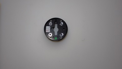
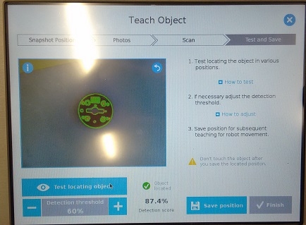
I was curious to see if I could use the vision system to find the through holes in a part. I tried teaching the M6 holes to the vision system, but I had to get very close to the part and this was limiting the field of view of the camera. So I decided to teach the entire part to the vision system, and I use an IF statement to teach several hole positions instead. I used a pallet function to pick up the 4 screws from the jig, and I used 4 IF statements to tell the robot where to insert the screws. In this demonstration, I am inserting the screws clockwise into the mechanical coupling.
https://www.youtube.com/watch?v=c6BjIs_UXtQ
As you can see, the part can be moved around since the vision system is looking for the part after picking up each screw.
*It would've been a good idea to use the aluminum fingertips without the silicone since the screws were sticking to the silicone!