Very cool. You could also 3D print a part if you have a printer. I have had issues getting stuff to print in the past at exactly 1:1 when we were making overlay templates.

The Dof Community was shut down in June 2023. This is a read-only archive.
If you have questions about Robotiq products please reach our support team.
If you have questions about Robotiq products please reach our support team.
 matthewd92
 Tyler_Berryman
Hey guys,


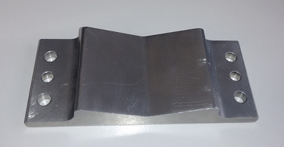
I know that a few people are having a tough time teaching shiny parts to the vision system due to reflections on the parts creating "ghost features" on the parts. I myself have seen this happen on aluminum parts that I trying to use for demos here at the office. So I figured, why not just use a 2D CAD drawing of the part to teach the part to the vision system. The following picture illustrates the problematic part :
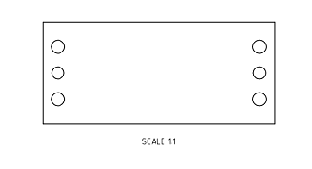
As you can see, there are some reflections on the surface of the part, and it was quite challenging to teach the part to the vision system. So I make a CAD model of the part and I also ignored a few features to simplify the geometry of the image template that will be generated by the visions system.
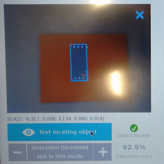
I printed the 2D CAD on a piece of blue paper using a 1:1 scale. I used a red piece of paper for the background when teaching this part to the vision system. For the 5 pictures, I used the red background and the blue piece of paper with the 2D CAD of the part. Then, when I got to the scan portion of the wizard, I used the real part to refine the image template for the part.
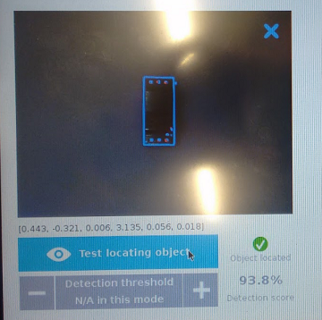
As you can see, the image template consists of the contour of the part and the 6 holes. I didn't want to teach the ridges on the part since I figured that this could also affect the detection score when the part will be on the outskirts of the field of view. As you can see, the vision system can detect the real part on a normal background.
What I would like to point out is that if your part is really reflective and you are having a hard time teaching your part to the vision system, you can use a 2D CAD of your part as long as it is in a 1:1 scale. This trick can also be used to erase ignore certain features that are problematic.