Home Programming

Discussion

Left ArrowBack to discussions page
ZachZach Posts: 7 Apprentice
All,

I've been really struggling how to do a 360 degree circle move with my tcp fixed to the orientation from the first point. Has anyone had success with this? If so how?

Comments

  • matthewd92matthewd92 Founding Pro, Tactile Sensor Beta Testers Posts: 1,267 Handy
    Are you trying to use the Polyscope circle move?  If so, you need two circle moves to make a 360 degree circle, 3 is even better, that is because you cannot do more than 180 degrees with the circle move.  Its best to limit it to 120 degrees.  We use them with pretty good success, you can choose the locked scenario when you are setting up the circle move and that will lock the torch orientation to be the starting torch orientation.  The trick is keeping that same orientation for each of the circle moves.
  • ZachZach Posts: 7 Apprentice
    edited March 2020
    I have been using the polyscope circle move.  Would you suggest using the endpoint of the first arc as the start of the second arc, or use the script command get_actual_tcp_pose() after the endpoint of the first move as the start of the second arc?
  • matthewd92matthewd92 Founding Pro, Tactile Sensor Beta Testers Posts: 1,267 Handy
    edited March 2020
    This is a very old code snippet that we did back in 2016 to make a dispensing application that needed to dispense silicon around the perimeter of a cup where we would be inserting a lid.  This is very crude but I will say it did work and we made a lot of parts with it for what its worth.  It can give you an idea of some of the manipulation that can be done. 

    This code basically takes a known center point and then we are calculating based on where we are around the circle in x, y and rz, we used a fixed z so that we could control the height of the bead but change it without needing to change the center point, it was defaulted to 0 and then adjusted up or down as needed.  You could also use the 


    <div>Loop 360 times
      rz≔rz+d2r(1)
      MoveJ
        If Loop_1<180
            y≔y-radius
        ElseIf Loop_1>180
          y≔y+radius
        If Loop_1<90
          x≔x-radius
        ElseIf Loop_1>90 and Loop_1<180
          x≔x+radius
        ElseIf Loop_1>180 and Loop_1<270
          x≔x+radius
        ElseIf Loop_1>270
          x≔x-radius
        point≔p[x,y,z,0,0,rz]
        pointTrans≔pose_trans(siliconeCent,point)
        pointTrans # This is the point that you are moving to with the MoveJ command, if you put this in a servoJ the motion would be much smoother, you would control the speed by changing the number of degrees for each step taken.  You would also need to change the loop condition to not be a 360 count loop but rather loop some multiple of 360/step size</div><div><br></div>

    Another way to get the x and y coordinates would be this function:

    <div>def nextArcPosition(theta, radius):
      x = radius * sin(theta)
      y = radius * cos(theta)
      return p[x, y, 0, 0, 0, theta]
    end</div>

    you could then assign the z  for each step into that function. WIth this function you need to pass in the total theta that you have gone, this is in radians, not degrees.

    </code><div><code><div>Loop 360 times
      rz≔rz+d2r(1)
      theta = theta + rz
      MoveJ
        nextPoint≔nextArcPosition(theta, radius)
        nextPoint[2]=zOffset
        pointTrans≔pose_trans(centerPoint,nextPoint)
        pointTrans # This is the point that you are moving to with the MoveJ command, if you put this in a servoJ the motion would be much smoother, you would control the speed by changing the number of degrees for each step taken.  You would also need to change the loop condition to not be a 360 count loop but rather loop some multiple of 360/step size</div><div><br></div>
  • matthewd92matthewd92 Founding Pro, Tactile Sensor Beta Testers Posts: 1,267 Handy
    Zach said:
    I have been using the polyscope circle move.  Would you suggest using the endpoint of the first arc as the start of the second arc, or use the script command get_actual_tcp_pose() after the endpoint of the first move as the start of the second arc?
    Actually you do not need a start point for the second arc, you use a point to get to the arc (inside the movep) and then the movec only takes 2 points, the via point and the end point, then you place the second arc segment with a via point and a end point.

    Here is an explanation from UR that does a pretty good job. https://www.universal-robots.com/how-tos-and-faqs/how-to/ur-how-tos/circle-using-movec/

    You will see that point 5 is the same as point 1 so they are only breaking the circle into 2 halves.

    MoveP
      waypoint1
      moveC
       waypoint2 #first via point (90 degrees)
       waypoint3 #Midppoint of full circle (180 degrees)
      moveC
        waypoint4 # second via point (270 degrees)
        waypoint1 # end waypoint also the same as the start point
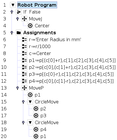
  • ZachZach Posts: 7 Apprentice
    I have tried the code you had just posted, but it just doesn't seem super smooth. I even tried a variable radius application, but still does not like the fixed orientation. code below.

  • matthewd92matthewd92 Founding Pro, Tactile Sensor Beta Testers Posts: 1,267 Handy
    That’s probably correct, the issue is your tool is not rotating as it goes around the path. Try adding a rotation to each of the translations for each point. 
  • ZachZach Posts: 7 Apprentice
    how would you recommend doing this?  I know that if i use the rz arrows on the tcp orientation tab it works, but I do not know how to do this within the program.

  • matthewd92matthewd92 Founding Pro, Tactile Sensor Beta Testers Posts: 1,267 Handy
    You would assign the rZ into the pose that you are translating.  This would move it around the circle.

    c[2], c[3], c[4], c[5]+d2r(90)]
    p3 = p[c[0]-r, c[1], c[2], c[3], c[4], c[5]+d2r(180)]
    p4 = p[c[0], c[1]-r, c[2], c[3], c[4], c[5]+d2r(270)]c = Center
    p1 = p[c[0]+r, c[1], c[2], c[3], c[4], c[5])
    p2 = p[c[0], c[1]+r, 
    That should cause the rotation you are dealing with as that will rotate the point around the Z axis of the center point at the same time you are moving the points away from the center.  Sometimes you will need to break the two actions apart and do one step before you do the other step but I would try this.

    You can also dop things like pose_add (base frame pose addition) or pose_trans (translation in the frame of reference of the first point in the function, generally aligned with the tool frame)

    The nice thing about the pose_trans function is that you can move things that are not aligned with the base frame of reference along the axes of that pose frame of reference.  So for instance if I teach a plane and it is not parallel to the base axis, maybe its rotated at 45 degrees as its a sliding table, I could move along the axes of that frame of reference by doing something like 

    pose_trans(someReferencePose, p[0,0.05,0,0,0,0])
    That would move the robot 50 mm in the Y axis of the frame of reference, not the base frame of reference. Using this I could have a variable that represents the center point of the circle.  I could then use that point to create the first point, I could then rotate the variable of the center point 90 degree and using the same offset create another point.

    
    c = pose_trans(c, p[0,0,0,0,0,d2r(90)]
    p3 = pose_trans(c, p[r,0,0,0,0,0])
    c = pose_trans(c, p[0,0,0,0,0,d2r(90)]
    p4 = pose_trans(c, p[r,0,0,0,0,0])c = Center
    p1 = pose_trans(c, p[r,0,0,0,0,0])
    c = pose_trans(c, p[0,0,0,0,0,d2r(90)])
    p2 = pose_trans(c, p[r,0,0,0,0,0])

    Hope that gives you some more insight into how to manipulate points with the robot using the built-in robot math functions.
  • ParshanParshan Posts: 1 Recruit
    Thank you guys for giving your time on this thread. It helped me too in solving the issue i was having and also saved some of my time that i can spend on the project. Thanks again. 
Sign In or Register to comment.
Left ArrowBack to discussions page